
Binary Clock Lets The Nixies Glow
Th2
Some clocks whisper. Some clocks beep. And then there’s the binary Nixie clock: a tiny neon bonfire that
tells time by turning math into mood lighting. It’s equal parts retro sci-fi prop and “I swear this is useful”
engineering projectbecause it is useful. It teaches you how time is represented in hardware,
how high-voltage displays behave, and how to design a system that’s both accurate and safe.
This guide breaks down what “Binary Clock Lets The Nixies Glow” means in practice: how binary time displays
work, why Nixie tubes need special handling, and how a modern build typically comes togetherfrom timekeeping
to drivers to that delicious orange glow. We’ll keep it practical, in-depth, and just sarcastic enough to
prevent solder fumes from becoming your entire personality.
What Is a Binary Clock, Really?
A binary clock displays time using bits (0s and 1s) instead of the usual digits. Each “bit”
is either off (0) or on (1). Add up the on bits, and you get a number.
The most beginner-friendly binary clocks don’t show the entire time in one big binary number (which would
be… ambitious). Instead, they use Binary-Coded Decimal (BCD): each decimal digit
(0–9) is represented by its own set of bits. That way, hours and minutes still behave like hours and minutes,
but each digit gets translated into a small binary puzzle.
BCD in one sentence
In BCD, the digit 7 becomes 0111 (bits for 1, 2, and 4 are on; 8 is off),
so the display lights three “bit indicators” to show “7.”
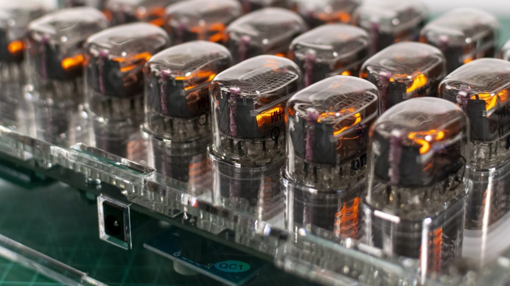
Meet the Nixie Tube: A Neon Number with Attitude
A Nixie tube is a cold-cathode indicator where each numeral is a shaped cathode inside a glass envelope.
Apply high voltage, select a cathode, and that numeral glows with a warm orange discharge that looks like
it was lit by nostalgia itself.
The catch (because there’s always a catch): Nixies typically need a high “strike” voltage to start glowing
and a somewhat lower voltage to keep glowing. They also run at low currentusually a few milliamps per lit
digitso you’re dealing with high voltage, not high power. Still: high voltage deserves respect.
More on safety soon.
So What Does “Binary Clock Lets The Nixies Glow” Look Like?
The core idea is simple: replace the usual LED dots of a binary clock with Nixie tubes. Each tube becomes a
“bit lamp.” When the bit is 1, the tube glows. When the bit is 0, it stays darkdramatic, minimalist, and
excellent for people who want their time-telling device to double as ambient lighting.
Common display layouts
-
BCD columns for HH:MM:SS: Each digit gets a vertical stack of bits (1, 2, 4, 8).
Practical and readable once you learn it. -
Binary blocks: Hours, minutes, seconds each get a group of bits (e.g., 6 bits for minutes).
This looks “more binary,” but is harder to parse at a glance. -
Hybrid “weighted Nixies”: Each tube is labeled (or internally wired) as a weight1, 2, 4, 8
and lights when that weight is used. It’s like a neon abacus.
For most builders, BCD wins because it’s the sweet spot between “cool” and “I can still function before coffee.”
Bonus: BCD maps cleanly onto classic Nixie driver approaches.
How You Read a Binary Nixie Clock
Let’s assume a BCD layout with vertical stacks. Each stack represents one decimal digit. From bottom to top,
the bit weights are usually 1, 2, 4, 8. If the 1 and 4 tubes are glowing, that digit is 5.
Example: reading “12:34” (hours and minutes)
- Hours tens = 1 → only the “1” bit is lit.
- Hours ones = 2 → only the “2” bit is lit.
- Minutes tens = 3 → “1” and “2” bits are lit (1 + 2 = 3).
- Minutes ones = 4 → only the “4” bit is lit.
The first time you read it, you’ll feel like you’re decoding a secret message from a friendly robot.
The tenth time, you’ll wonder why normal clocks are so… loud about it.
The Hardware Anatomy: What Makes the Glow Happen
A binary Nixie clock is basically four subsystems wearing a trench coat:
(1) timekeeping, (2) logic/control, (3) high-voltage generation,
and (4) high-voltage switching.
1) Timekeeping: the “truth” source
You need a stable time reference. Many builds use a dedicated RTC (real-time clock) chip/module, often with a
temperature-compensated oscillator for better long-term accuracy. A popular “precision” class RTC can be accurate
enough that it drifts on the order of a minute per year under typical conditions, which is wildly good for a
small, low-power device.
If you want “set it and forget it” accuracy, you can add periodic synchronizationvia network time (if your clock
has connectivity) or a radio time signal receiver (region dependent). Otherwise, a good RTC plus a sane set routine
is usually enough.
2) Control logic: microcontroller, FPGA, or classic logic
Something has to read the time and decide which bits should be on. Most hobby builds use a microcontroller because
it’s flexible: you can add button menus, brightness control, fancy transitions, or a “night mode” that dims the
display so your clock doesn’t cosplay as a toaster oven at 2 a.m.
The control logic outputs a set of on/off decisions for each bit tube. That output is low voltage. Nixies are not.
Which brings us to…
3) High-voltage power supply: making 5V/12V become “Nixie happy”
Nixie tubes generally want a high-voltage DC rail (often in the neighborhood of ~150–180V, depending on tube type
and driver scheme). Most modern builds generate this using a boost converter (an inductor-based step-up supply).
The design goals are:
- Stable output voltage with predictable behavior as tubes switch on/off.
- Enough current headroom for the maximum number of simultaneously-lit tubes.
- Manageable noise so your clock doesn’t become an AM radio jammer.
- Safe layout with proper spacing and insulation practices.
The HV supply is one place where “close enough” can become “mysterious flicker” or “why does it reset when
seconds change?” Good decoupling, sensible grounding, and careful routing matter.
4) High-voltage switching: selecting which cathodes glow
Each Nixie numeral is a cathode that you pull “on” via a driver. You can do this a few ways:
-
Classic BCD-to-decimal driver ICs: Feed 4-bit BCD, and the chip sinks current for one of ten
cathodes. This is historically popular and clean for digit-based displays. -
HV shift registers / HV driver arrays: Serial data in, many high-voltage outputs out.
Great for custom bit layouts. - Discrete transistors: Totally doable, but wiring can become… emotionally significant.
For a binary clock, the “digits” might simply be the numeral “1” glowing (bit = 1) or the tube being off (bit = 0).
That means you can treat each tube like a controlled lamp: one cathode used, others unused. That looks awesome,
but it introduces a long-term consideration: unused cathodes can age differently than used ones.
Display Strategy: Static vs. Multiplexing (and Why You Should Care)
There are two common ways to drive multiple Nixie tubes:
Static drive
Each tube has its own driver and can be lit continuously. It’s simple, bright, and easy to reason about. The trade-off
is cost (more drivers) and PCB area.
Multiplexing
You rapidly switch which tube is on, many times per second, so it looks like all are lit at once. This can reduce driver
count and wiring, but it adds complexity: timing, ghosting, brightness balancing, and greater sensitivity to layout noise.
For a binary Nixie clockwhere “bit clarity” mattersstatic drive is often the friendliest path. Multiplexing can still
work beautifully, but it rewards careful engineering.
Practical Design Tips That Save Your Sanity
Budget your current like you budget your weekend
Figure out the maximum number of tubes that could be on simultaneously (worst case). In BCD, the “8” bit isn’t always
used, but don’t rely on luck. Design for the maximum realistic load and give yourself margin.
Use proper current limiting
Nixies are glow-discharge devices with negative resistance behavior, so they need a current-limiting elementoften a resistor
in series with the anode. Pick values based on your tube’s recommended operating current and your HV rail.
Give high voltage the space it deserves
High voltage doesn’t need high drama, but it does need spacing, clean routing, and insulation practices that prevent arcing,
leakage, or accidental contact. Keep HV nets separated from low-voltage logic, and don’t run HV traces under your microcontroller
like you’re trying to add “spicy” to your debugging session.
Plan for a “digit exercise” routine
If your design uses only one numeral (like always lighting “1” for bit-on), consider occasionally cycling through other numerals
if the tube and driver design allow it. Many clocks include a short “slot machine” style routine to keep cathodes from becoming
neglected over long periods.
Brightness control: because eyes are not rated for 170V
You can control brightness by adjusting duty cycle (especially in multiplexed builds), altering tube current within safe limits,
or changing the HV rail slightly (with caution). A “night dim” mode makes the clock livable in real bedroomsunless you’re going
for the “interrogation room chic” aesthetic.
Accuracy and Drift: Why Your Clock Lies (a Little)
Even good clocks drift. A simple quartz oscillator can be off by tens of parts per million, which adds up over days and weeks.
Better RTCs reduce that drift dramatically, and some systems include calibration or compensation features.
If your clock supports periodic synchronization (radio time signal or network time), you can correct drift automatically.
If not, you can still design a pleasant user experience: easy setting, optional calibration offset, and a drift check once in a while.
Think of it as dental hygiene, but for seconds.
Troubleshooting: When the Glow Gets Weird
Symptom: tubes don’t light at all
- Verify the HV rail with a meter (carefully).
- Confirm polarity and ground references.
- Check the anode resistor path and driver wiring.
Symptom: flicker, dim glow, or random resets
- Your HV supply may be sagging under loadadd margin or improve regulation.
- Improve decoupling and grounding; keep HV switching noise away from logic.
- Watch for multiplex timing issues if you’re scanning tubes.
Symptom: “ghosting” (wrong digits faintly visible)
- Check driver off-state behavior and leakage paths.
- Consider snubbers or improved switching strategy in multiplexed designs.
- Review PCB cleanlinessflux residue can matter at high voltage.
Why This Project Is Worth It
A binary Nixie clock is the kind of build that teaches you something every step of the way:
- Digital representation: bits, BCD, mapping, and human-readable layouts.
- Power electronics: boost conversion, load behavior, and noise control.
- High-voltage design discipline: spacing, insulation, safe measurement habits.
- Product thinking: readability, brightness, setting UX, and long-term reliability.
Also, it looks outrageously cool. That’s not engineering. That’s just good taste.
of Hands-On Experience: What It’s Like Building One
Here’s what builders tend to discover when they actually sit down to create a binary Nixie clockespecially the first time
they combine “cute little time display” with “high-voltage neon hardware.” First, you’ll realize that the mechanical layout is
not an afterthought. Nixie tubes are three-dimensional, they cast shadows, and their glow looks different depending on viewing
angle. A binary layout that seemed perfectly logical on paper can become visually confusing once the tubes are mounted. Many people
end up shifting spacing, aligning columns more clearly, or adding subtle separators so your eyes can chunk the time into HH:MM:SS
without doing gymnastics.
Second, you’ll learn that high voltage is mostly about process, not panic. You don’t need to be scared, but you do need
habits: measure with one hand when practical, discharge capacitors before touching, keep exposed HV points away from fingers and
curious metal tools, and don’t “just test something real quick” at midnight when your brain is running on vibes alone. The good
news is that once you treat HV like a disciplined adult, it becomes routinelike wearing a seatbelt, but for your eyebrows.
Third, you’ll probably iterate on the power supply more than you expected. A Nixie clock can work “okay” with a supply that
technically reaches the target voltage, but it will work beautifully when the supply behaves under switching load.
Builders often notice that a slight redesignbetter inductor choice, cleaner layout, improved filtering, or simply more headroomcan
turn flickery, temperamental glow into crisp, stable illumination. This is where you start appreciating why power electronics is
its own specialty and why “it’s only a few milliamps” is not the same as “it’s easy.”
Fourth, you’ll discover that software polish matters. A binary Nixie clock is readable once you learn it, but small touches make it
far more pleasant: a short “top-of-minute” animation that doesn’t ruin readability, a brightness schedule that dims at night, a quick
way to enter set mode, and maybe an optional “training mode” that briefly flashes the conventional time on a separate indicator (or
via a companion screen) while you’re learning. The project stops being “a circuit that tells time” and becomes “a product you like
living with.”
Finally, you’ll understand why people get emotionally attached to these builds. The glow feels alivewarm, analog-looking, and a little
theatrical. When you finish the last calibration and the bits click over cleanly at the minute boundary, it’s hard not to grin.
You didn’t just make a clock. You made a tiny museum exhibit that runs on math.
Conclusion
“Binary Clock Lets The Nixies Glow” is a perfect mashup: binary logic for the brain, Nixie glow for the soul. Whether you build it as a
BCD-based HH:MM:SS layout or a more daring binary block, the principles stay the same: keep time accurately, generate a stable HV rail,
switch cathodes safely, and design the display so a human can read it without filing a support ticket with their own forehead.
Do it right and you’ll get a clock that’s practical, teachable, and wildly photogenic. Do it wrong and you’ll still learn something
mostly about why smoke is a bad debugging tool. Either way, the Nixies will glow… assuming you were nice to your power supply.